by Gerrit Barnard, Comtest
Recent observations of urban-domestic and SME offices, sporting row upon row of solar panels, clearly shows evidence of the increasing trend by these sectors, to switch from traditional sources of energy to alternative or clean energy – in this instance, solar energy.
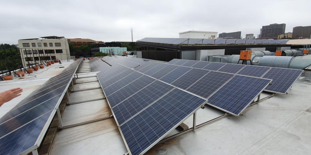
Solar panels are made up of cells joined together in series and relayed to a control box. And, of course, when connected in series, the panel is only as good as the weakest cell. If one of these cells fails, it affects the overall performance of the entire panel. The case study illustrated here is of a roof-top installation situated on the Old Mutual Building, Johannesburg.
Installation
Close attention should be paid to the installation of panels. If, as in the case illustrated in Image 1, the panels are located too close to the concrete roof surface, they are affected by radiated heat. This is evidenced by quite a few cells failing along the bottom of the panels. In this installation there is no more than 15cm clearance between the roof and the bottom edge of the panels. For this installation to be successful and give better performance, the panels would have to be raised, allowing for better ventilation and less heat build-up at the bottom. Fluke’s IRR1-Sol Solar irradiance meter not only measures panel performance and temperature, but it is specifically engineered to perfectly align solar panels for optimum performance. It accurately measures the irradiance – the angle of the panel vs angle of the sun.
Panel Inspections
Ideal conditions for inspecting solar panels are clear, sunny skies for optimum readings. Faulty cells would be a lot warmer because overcast conditions do not produce maximum performance.

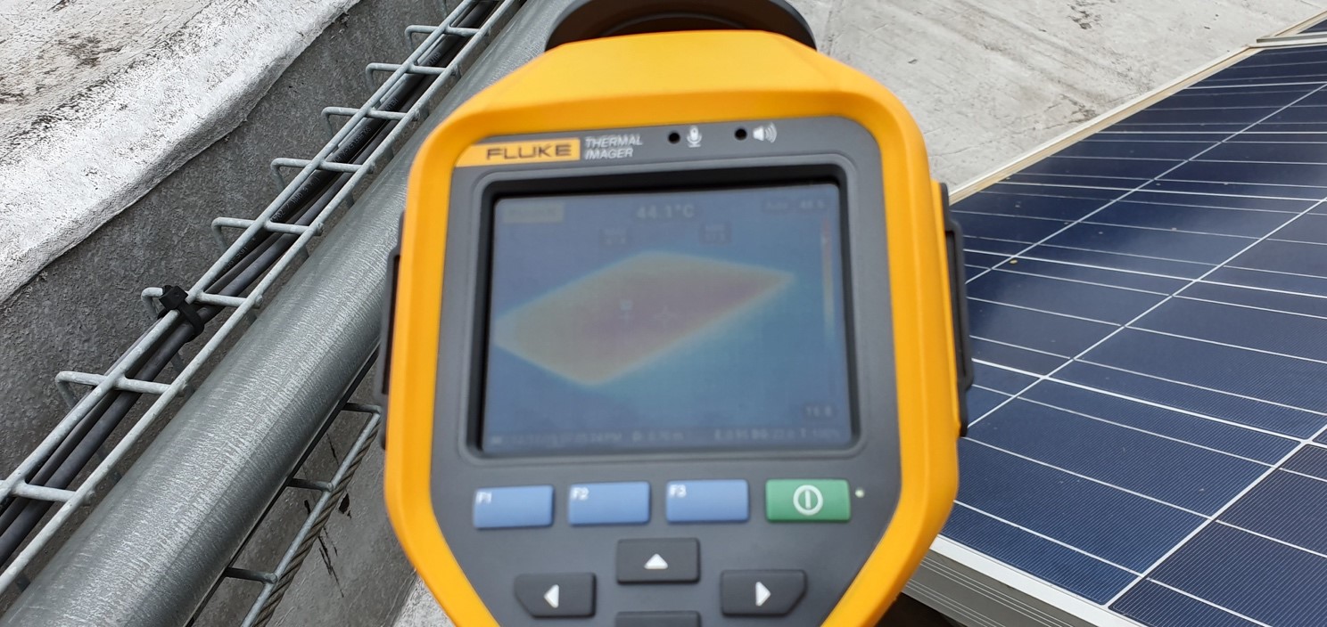
This image clearly illustrates the advantages of a thermal imager. Looking at the panels with the naked eye, one would not pick up any anomalies. But, with a good imager, one can very clearly see the problems with this panel. One block is heating up relative to the rest of the cells. This indicates a faulty panel, and that one of the cells that are connected in series has failed, dropping the performance of the panel. This panel needs to be replaced.
Access to panels
In order to walk and scan the panels, one needs access to the panels. The Fluke 401 or TiS60 imagers suit this application well, as long as the installations are spaced so that maintenance technicians are able to walk along the series and scan the panels individually. Manually tested, the Ti’s pictures are saved with time and date, as well as tagged with voice memo recordings of where the panels are located. The photos can then be downloaded so that the technician knows exactly where to find the particular problem panel. One can even take the serial number of the panel, as well as 4 extra photos of the panel being worked on.
Walk access to solar panels is not always possible, this then calls for drone technology, that flies over the panels, and views them remotely. An example of this would be the Northern Cape’s vast solar arrays.
Panel Lifetime
Be aware that solar panels do degrade their output performance over time, and they definitely have a finite lifecycle, thus regular maintenance is absolutely necessary.
Other devices technicians use to test and troubleshoot solar installations:
- Fluke 393FC Clamp meter/troubleshooting tool measures load and voltage levels.
- Fluke 1775 PQ Logger measures power inverter efficiency, power output and power quality of solar systems.
- Fluke BT520 measures and tests the batteries in solar applications, and identifies the weakest battery in the string, allowing owners to choose to replace only one particular battery, if needed.
Contact Comtest, Phone 010 595-1821, sales@comtest.co.za , www.comtest.co.za
Facebook: bit.ly/3iuk4cg
YouTube: bit.ly/2V4nc6j
LinkedIn: bit.ly/3rpTu86
HashTags: #Solarsolutions #Fluke #Comtest #Solar


